Technical Information
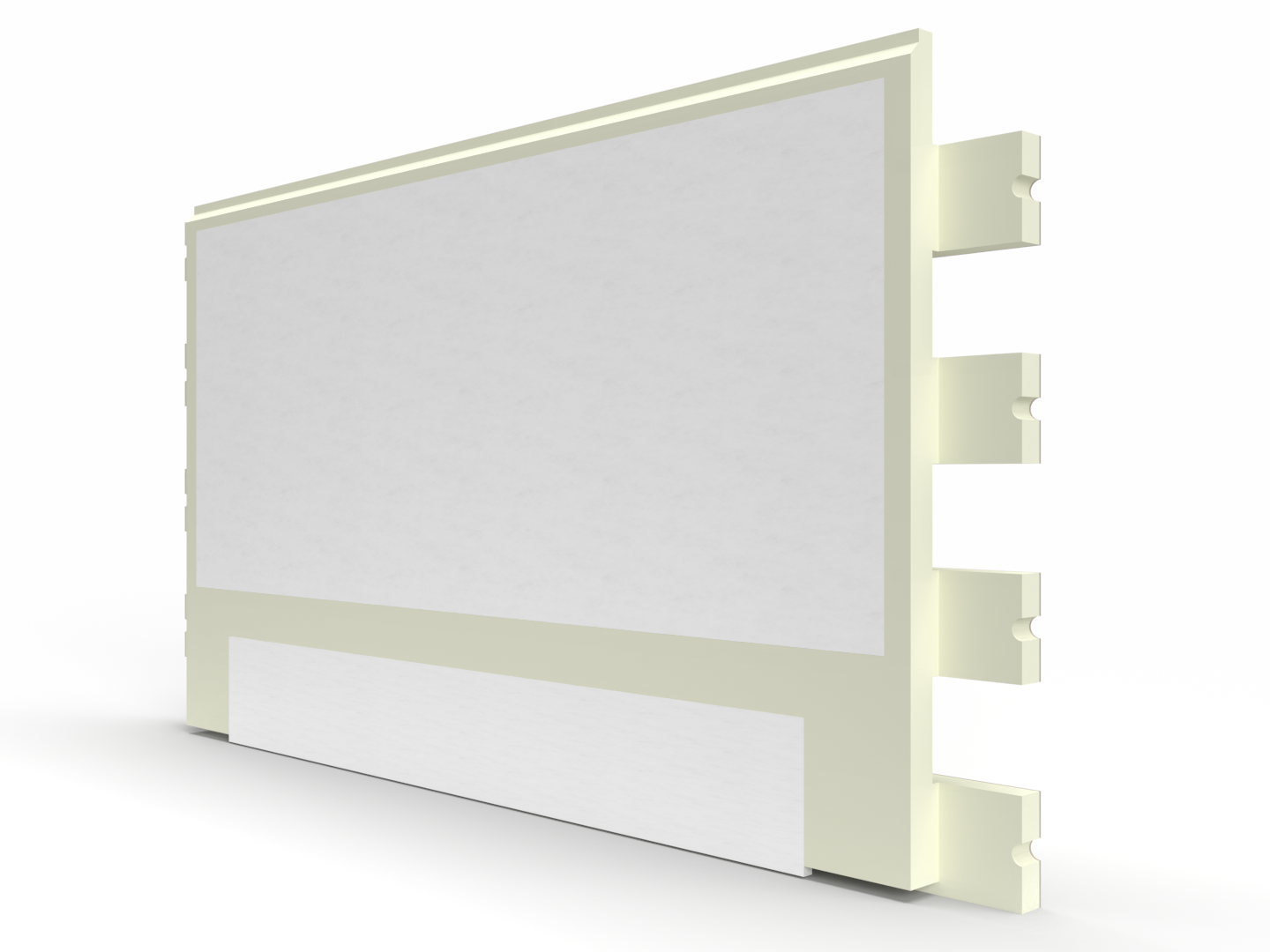
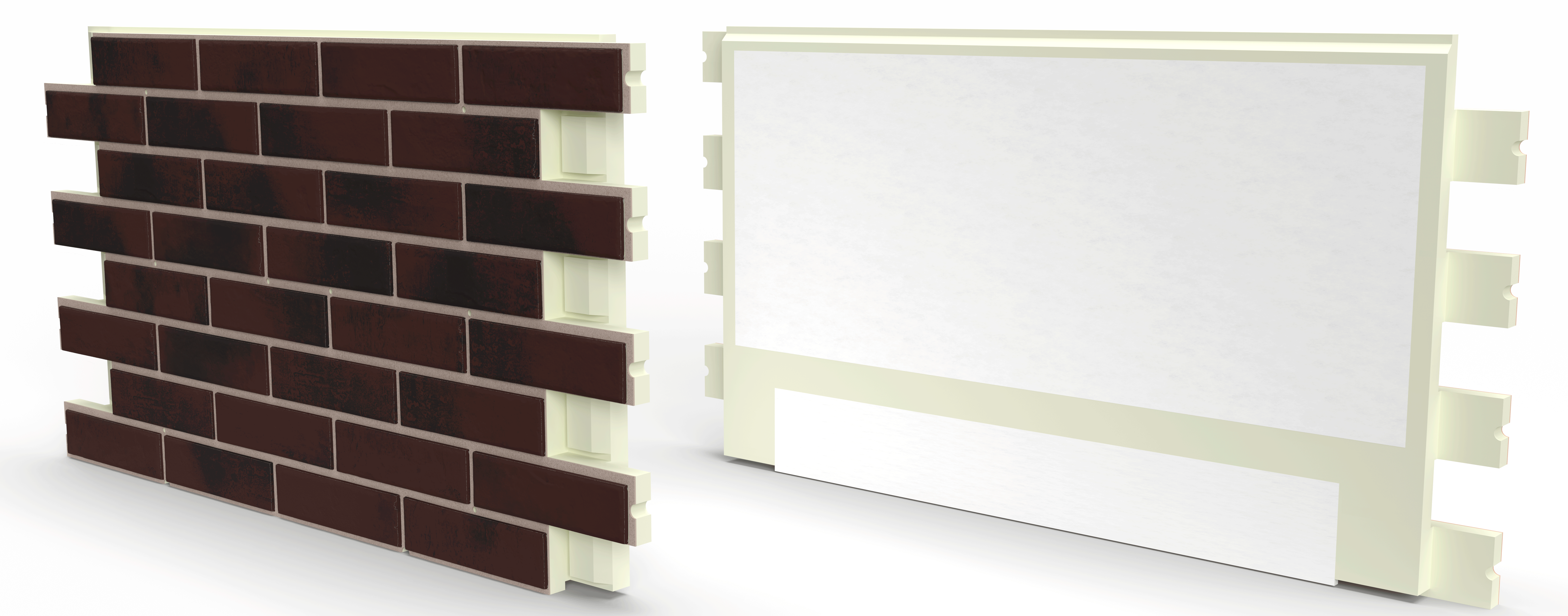
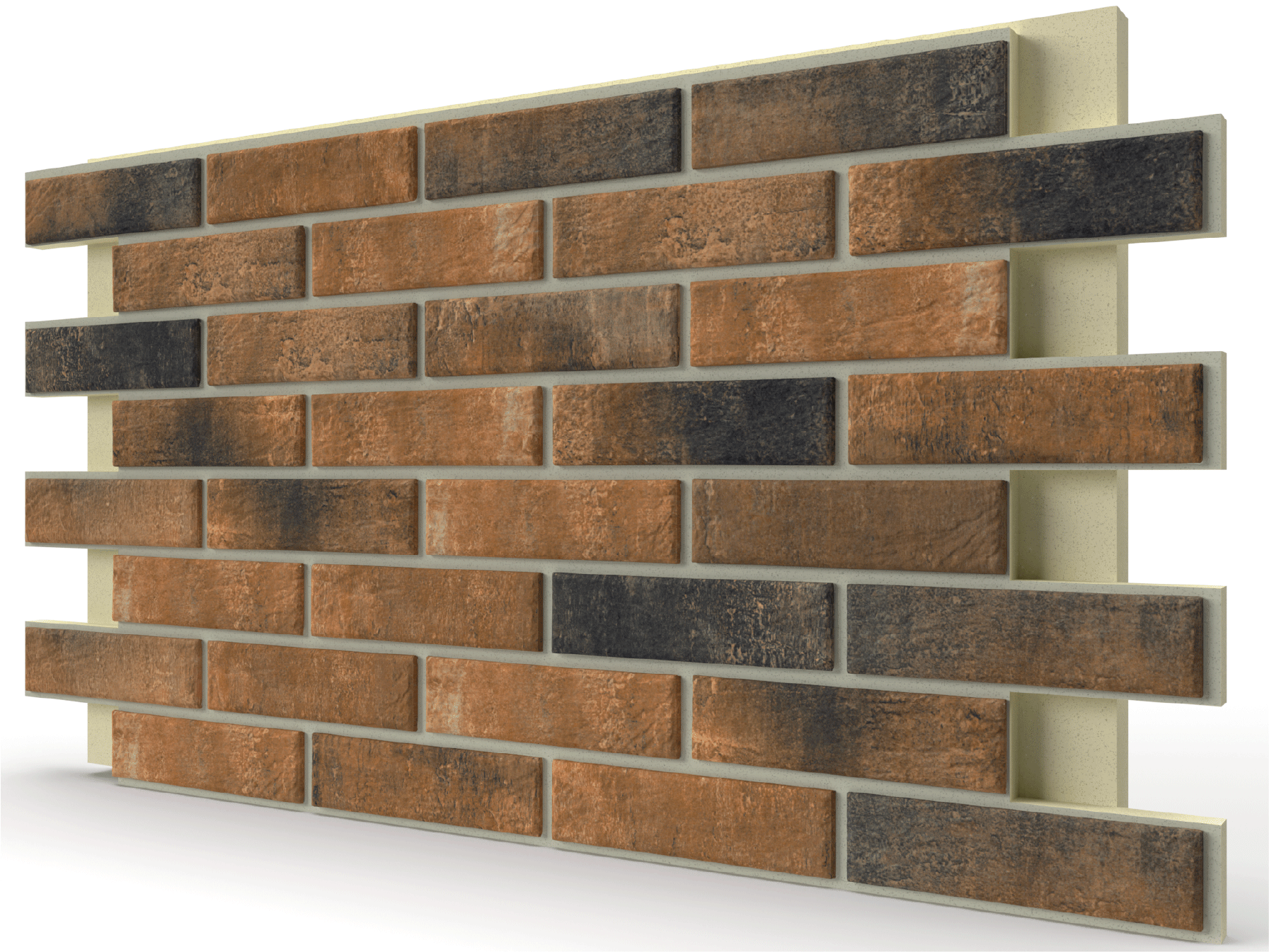
Composition of Thermal Panels
The use of ceramic tiles on the facade of the house will create a solid appearance protected from the influence of any weather conditions.
Quartz sand helps protect polyurethane foam from the effects of ultraviolet radiation and ensure adhesion of grouting solutions.

Magnesium Oxide (MGO) boards provide panel reinforcement and protect against deformation. MGO is non-flammable and hydrophobic material.
Polyurethane foam ensures the highest energy efficiency of the building. PUF is completely safe, hypoallergenic and does not support combustion.
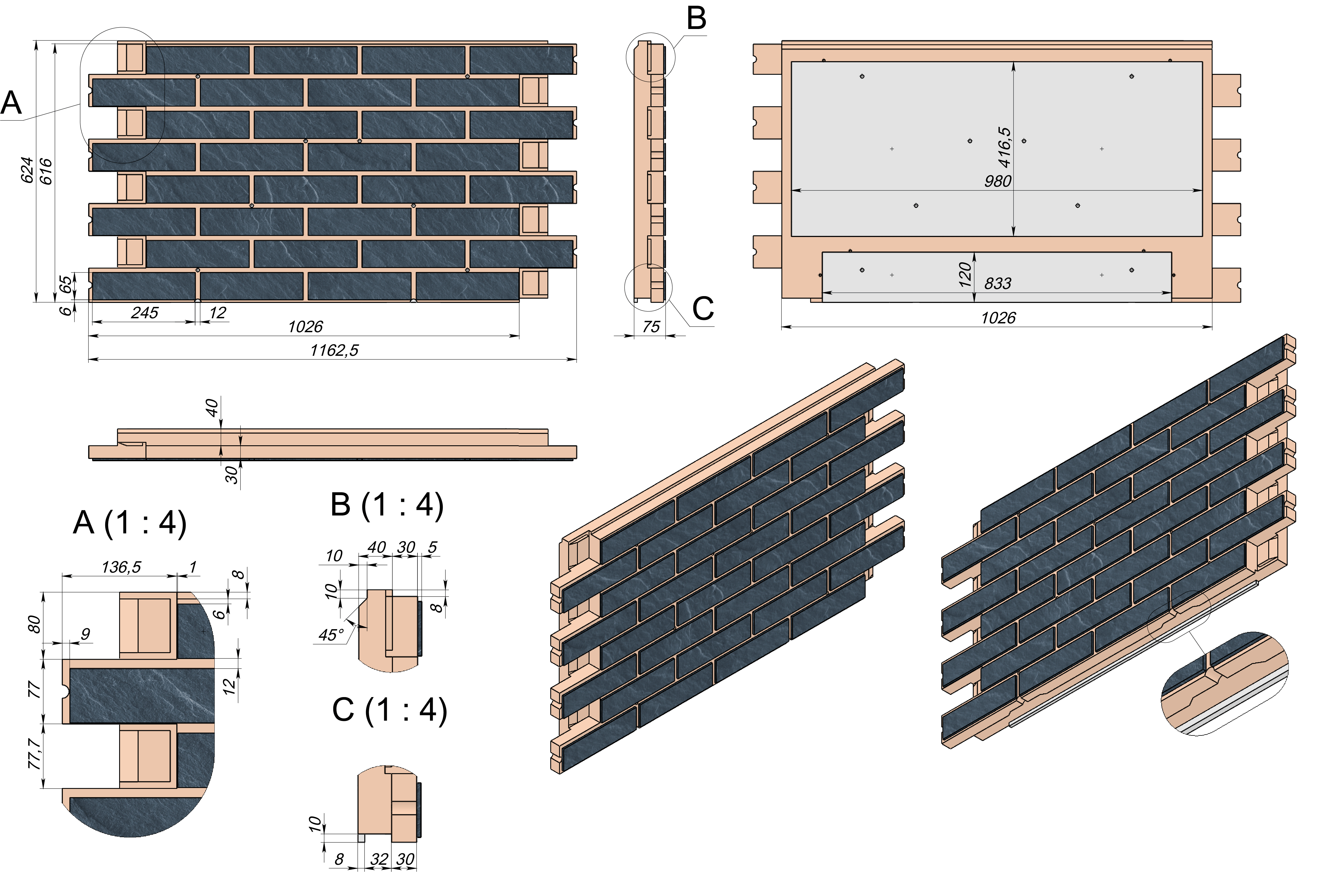
Thermal panel Drawing
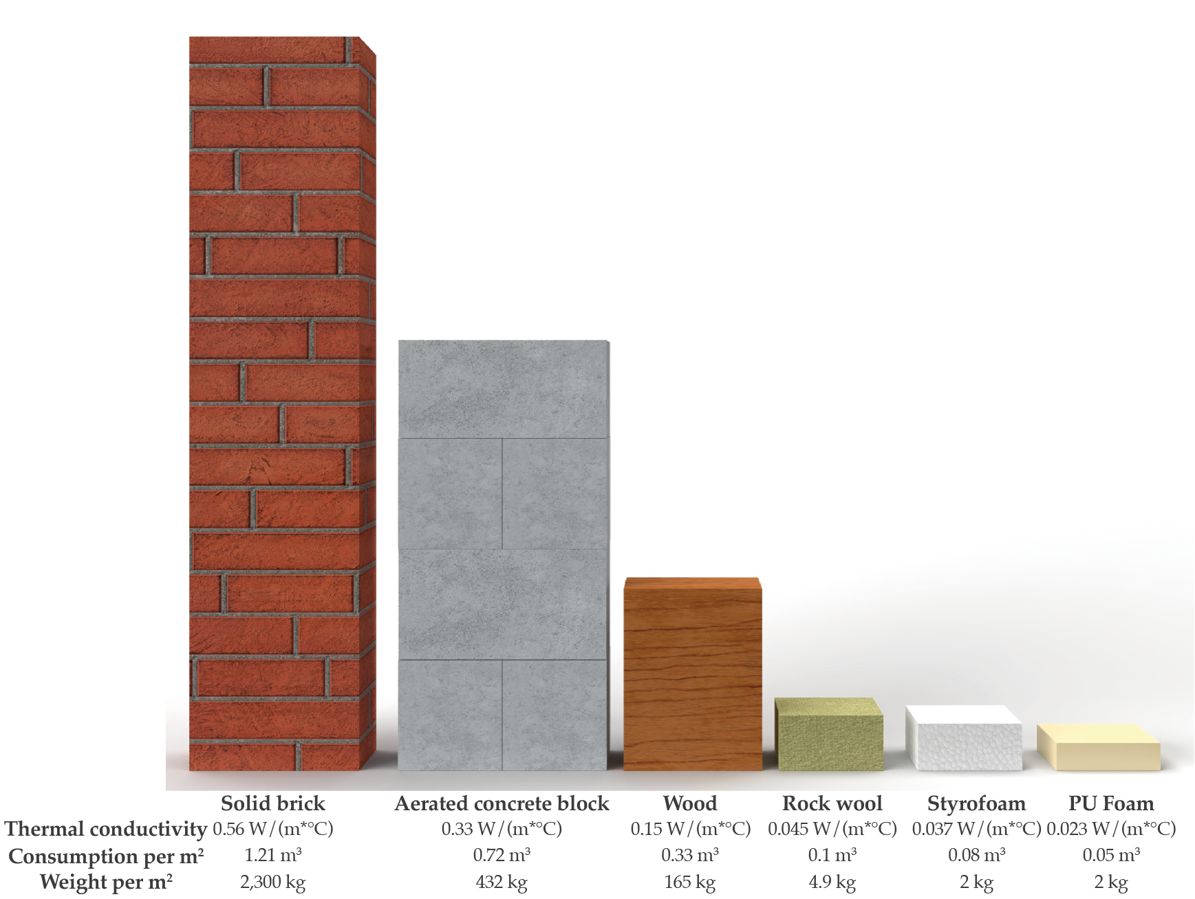
Comparison of Thermal Conductivity
Polyurethane foam used in thermal panels has the lowest thermal conductivity, namely 0.021-0.023 W/(m²*°C). A 50mm thick panel is equivalent to 121cm of solid brick masonry.
From the image we can see that significantly less polyurethane foam is required, both in volume and weight, to provide the appropriate level of insulation. This allows you to significantly reduce the cost of preparing the foundation, as well as eliminate additional subsystems.
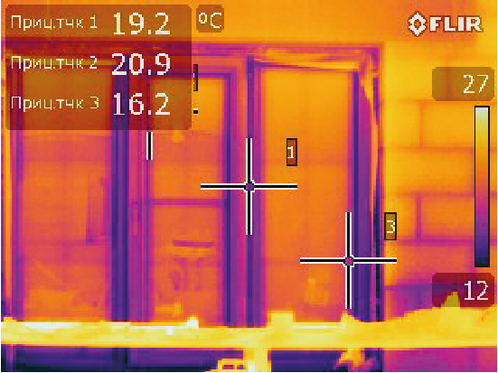
Energy efficiency of Thermal panels
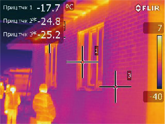
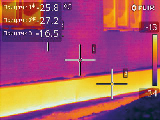
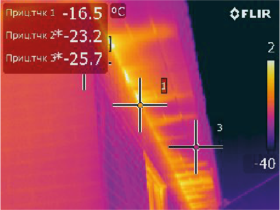
After installing Thermal Panels, we conduct an actual study using a thermal imager to evaluate the effectiveness of thermal insulation. In the above example, the outside temperature was -28°C. The required temperature inside the building is 21°C. As we can see from the results recorded by a thermal imager, after installing thermal panels, the only remaining places through which heat loss occurs are: Basement (foundation), window joints and roof joints. This case clearly shows the difference in thermal conductivity and thermal resistance in comparison with concrete walls (since the foundation is made of concrete).
Data obtained by a thermal imager from outside the building
To assess the energy efficiency of using thermal panels, we carried out a thermal calculation using the example of a room with an area of the enclosing structure (walls) of 200 m². This facade approximately corresponds to a house with an area of 100 m2
This calculation shows that when using polyurethane foam thermal panels, it can reduce the heat loss of the building envelope by more than 2 times.
Due to the fact that the estimated efficiency of the air conditioner is 90%, the actual energy consumption when using 50 mm polyurethane foam thermal panels will be reduced by 1.16 kWh

Benefits of Thermal Panels
- PU foam Thermal panel - is a ready-made design that is easy to install and does not require additional subsystems;
- The PU foam Thermal panel has the highest installation speed among all existing facade systems;
- The light weight and small thickness of PU foam Thermal panels allow to optimize the cost of preparing the foundation of a building;
- The high accuracy of the geometry of PU foam Thermal panels allows to avoid defects during installation and optimize the cost of installation work;
- PU foam Thermal panel has high wear and weather resistance;
- The highest rate of adhesion of tiles to insulating material;
- Polyurethane foam is the only biologically safe insulation;
- Polyurethane foam does not caking and has the longest service life among insulation materials;
- PU foam Thermal panels have minimal water absorption compared to other insulation materials, which guarantees the stability of the insulating properties;
- PU foam Thermal panel is not subject to combustion;
- The service life of PU foam Thermal Panels is up to 100 years.
Recycling and Sustainability
All components of PU thermal panels, namely: Ceramic tiles, Quartz sand, Polyurethane foam and MGO board are suitable for recycling.

Methods for recycling PU foam
Mechanical method - grinding to granules of a certain size, which are then mixed with binders. The resulting material has good mechanical characteristics and is widely used in the production of products: underlays for carpets, parts for chairs and armchairs, incl. automotive and aviation - armrests and headrests, etc.
Glycolysis method - is a process in which macromolecules are split into ether and/or urethane bonds, and linear macromolecules are destroyed. The resulting products are used as additives in asphalt and asphalt concrete mixtures, mastics for various purposes, adhesives, varnishes, paints, etc.
Pyrolysis method - heating to a certain temperature without air access. As a result of pyrolysis, polyurethane foam decomposes; The final products are gases and oils of various compositions, which can be used as chemical raw materials or fuel.
Carbon Footprint
The total Carbon footprint generated by production is fully compensated after 32 days of using thermal panels.